There are six types of refrigerant flow controllers: 1) manual expansion valve 2) automatic expansion valve 3) thermostatic expansion valve 4) capillary tube 5) low pressure side floating valve 6) high pressure side floating valve
Refrigerant controllers perform two tasks regardless of their type:
1- Allowing the liquid refrigerant to flow from the liquid pipe to the evaporator with the same intensity as liquid evaporation in the evaporator.
2- Creating a pressure difference between the high-pressure and low-pressure sides of the system so that the refrigerant can be distilled in the condenser at the same time when it evaporates under low pressure in the evaporator.
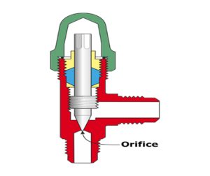
1) Manual expansion valve
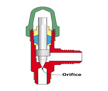
They are a type of needle valves in which the intensity of the refrigerant flow depends on the pressure difference in the valve opening and the opening of the valve hole. In this way, the constant pressure difference in the valve, regardless of the pressure or loading of the evaporator, the flow through the system will remain constant. The main disadvantage of manual expansion valves is their insensitivity to system load changes. Therefore, to avoid emptying or overfilling the system when the load changes, it must be adjusted manually. Also, when the compressor turns on and off, the valve must be opened and closed.
2) Automatic expansion valve
By gradually filling the evaporator with liquid refrigerant in response to changes in the refrigeration load, it keeps its pressure constant. will be
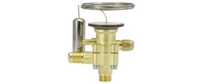
3) Thermostatic expansion valve
Thermostatic expansion valves are the most widely used type of refrigerant controllers due to their high efficiency and ease of adaptation to any refrigeration application. While automatic expansion valve operation relies on constant evaporator pressure, thermostatic expansion valve operation depends on constant superheating of vapor exiting the evaporator, a phenomenon that allows the evaporator to be completely full of refrigerant under all system load conditions.
4) Hair tube
It is the simplest device to control the refrigerant flow and consists of a certain length of very small diameter pipe that is placed between the condenser and the evaporator and usually instead of the liquid pipe. The capillary tube resists the flow of liquid refrigerant from the condenser to the evaporator due to the high frictional resistance due to its long length and small diameter, as well as the suffocation phenomenon caused by the gradual evaporation of the refrigerant liquid in the pipe due to the reduction of the pressure to less than the saturation pressure. The flow control of the passing refrigerant keeps the pressure differential between the two at the required level.
Other devices in the refrigeration cycle
Hand valves
Task: block the flow
Installation location: on the liquid line or any path that needs to be closed during repairs.

Filter/drier
Task: filtering refrigerant (particles and a little refrigerant)
Installation location: on the liquid line or suction line
electric valve
Task: blocking the flow of refrigerant
Installation location: on the liquid line, the closest possible distance to the expansion valve or on any line that needs automatic closing.

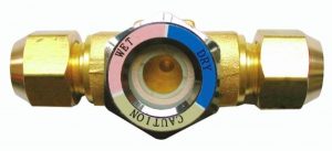
sight glass
Task: show the flow of liquid
Installation location: on any line where liquid flow needs to be observed.
Oil separator
Task: separating oil from exhaust gas
Installation location: on the discharge line between the compressor and the condenser
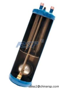

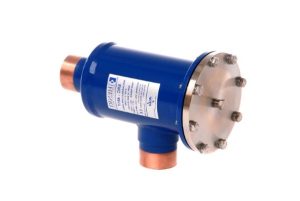
The compressor discharge gas, which naturally also carries oil, enters this tank and the oil, being liquid and heavy, goes under the tank and causes the floater valve to open. The outlet of this valve is connected to the compressor crankcase. Because in the oil separator, the discharge pressure is compressor and in the crankcase is the suction pressure, so when the floater valve is opened, the oil is discharged into the crankcase due to the pressure difference.
If there is liquid refrigerant in the oil separator, this liquid enters the compressor like oil and causes severe problems, for this reason, the oil separator must be installed in a warm place. If the refrigeration system works in winter, in When the compressor is turned off, the gas in the oil separator can also be distilled and enter the crankcase. It is suggested to install an electric valve in the path of the separator pipe and the compressor crankcase, and the power of this valve should be taken from the compressor in order to Close this valve when the compressor shuts down.
Accumulator
Task: preventing refrigerant from entering the compressor
Installation location: on the suction line between the evaporator and the compressor
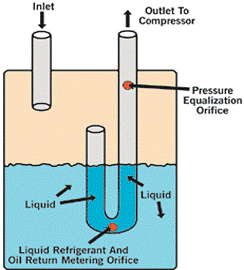
Below the outlet pipe there is a small hole that returns the oil in the accumulator to the compressor, and at the top of the pipe there is another small hole for balancing the pressure. When the liquid collects under the accumulator and the compressor is turned off, the liquid enters the pipe through the hole under the pipe and the level of the liquid in the pipe and the accumulator becomes the same. When the compressor is turned on, this column of liquid will immediately enter the compressor.
The pressure balancing hole causes the pressure before and after the liquid column to be equal, and therefore, during the start of the compressor, this liquid column remains suspended for a few seconds and will have time to evaporate.
Pressure control
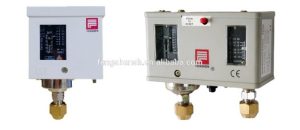
Task: control (limiting) pressure / Installation location: high and low pressure branches are connected to this device.
Oil pressure control
Task: oil pressure control in the compressor / installation location: high and low oil pressure branches are connected to this device.

Thermostat
Task: temperature control / installation location: on the return of the cooling fluid to the evaporator

One-way valve
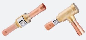
Function: prevent undesirable return of refrigerant or oil
Seismic
Task: preventing the transmission of compressor vibration to the lines / installation location: on the suction and discharge line of the compressor
Installation method: parallel to the compressor crank horizontally

receiver
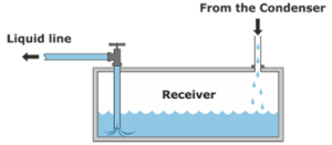
Function: place of additional refrigerant in the system / installation place: between the condenser and the expansion valve
When the expansion valve is closed, excess refrigerant accumulates in the receiver, if the receiver is not placed in the system, the excess refrigerant accumulates in the condenser and reduces its thermal level. If the level of the condenser is reduced, the discharge pressure will rise.
.




آخربن دیدگاه ها: